A multilayer light reflection model is designed based on the stacking unit of oxide films, metallic films, and a vacuum gap. By tuning the number of units, the thickness of each layer, and the stacking sequence, an effective light-reflection medium is expected to be applied to the building windows or vehicle windows. Beyond the model design, the genetic algorithm is cooperated to optimize these variables. In the python-based simulation, an initial demonstration is introduced to pave a direction for maximizing the light reflectance.
Introduction
Light is a daily observation that has been interpreted into several categories: geometrical optics; light as a wave; light as electromagnetic radiation; and the quantum theory of light. In the engineering space, the first two interpretations are often used for device design or measurement.
In geometrical optics, we take light as rays. When the light traveling in one transparent medium encounters a boundary with a second transparent medium, a portion of the light is reflected and a portion is transmitted into the second medium. The transmitted portion of light changes the traveling direction. It follows the law of refraction:
\[{n_1}sin{\theta_1} = {n_2}sin{\theta_2}\] 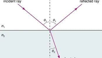
Fig. 1. The schematic of the light reflection and refraction
The index of refraction (\(n\)) varies across different mediums (air, water, or glass). The value for any medium is a dimensionless constant equaling the ratio of the speed of light in a vacuum to its speed in that medium.
Take light as a wave, which contains vibration energy. We can use a harmonic wave equation to represent the light
\[\Phi(x,t) = A cos(\frac{2\pi x}{\lambda} - 2\pi ft)\]the wavelength \(\lambda\) of the wave is the physical separation between successive crests. The maximum displacement of the wave, or amplitude, is denoted by \(A\). The number of oscillations per second is the wave frequency \(f\). The traveling speed in a medium (\(v\)) equals the distance between crests multiplied by the frequency (\(v = \lambda f\) ).
Because the refraction indexes for different materials are different. The potion of the transmitted light can be adjusted by changing the characteristics of the material. One of the strategies is designing the multilayer medium and increasing the number of reflection-refraction interfaces. Based on this approach, there is a possibility of minimizing the transmitted portion of the light which is preferred in the summer hot weather. By tuning the refraction index to different stacking layers, the number of stacking layers, and the thickness of each stacking layer, an effective light-reflection medium is expected to be used on the building windows or vehicle windows.
With this in said, a model of multilayer medium reflection is designed to optimize the light reflection. The variables are the number of stacking layers, the material for each stacking layer, and the thickness of each layer. In order to maintain the transparent property and the mass efficiency, the thickness is expected to be controlled in nanometers.
Model Set-up
Some assumptions need to be revealed before the model setup:
- The intensity of the light is quantified as a relative ratio by the transfer-matrix method.
- The interaction at the interface for the back-ward traveling light potion is not considered.
- The light wave range defaults as the visible light.
The material for the stacking layers can be metal: (silver, gold, aluminum, copper, etc.) and oxide compounds (alumina, silica, titanium oxide, etc.). In general, the metallic film gives a good reflectance. However, due to the plasma effect, the metals show a poor reflection at the ultraviolet and short visible wavelengths. In the model, we use silica, alumina, silver, and titanium oxide as the stacking unit pair because the TiO2, SiO2, and Al2O3 do not absorb light in the visible and near-infrared range. For some conditions, the vacuum gap inside the glass can stop the noise propagation. In return, it increases the interaction interfaces. Therefore, we also design a vacuum gap in the stacking unit to increase the ability of both light reflection and noise shield.
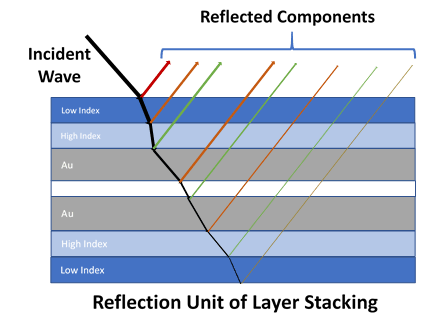
Fig. 2. The refection unit of layer stacking
According to the light traveling speed v = λf, the light of different wavelengths results in different refraction indexes in a specific medium. So, the input data include the thickness of the constructing layers, the refraction index of each layer, the incident angle, and the wavelength range. In the model, the input data matrix is set as [n_list, d_list, th_θ, lam_vac] which contains the geometrical information of the multilayer stacking. Using the transfer-matrix method, the calculation is based on the core “tmm_core.py” (referred to Steve Byrnes as “Multilayer optical calculation”). The output data is presented as reflectance vs. wavelength, transmission vs. wavelength, absorption vs. wavelength, and extinction vs. wavelength.
Starting with a Demo
Fixing the thickness of the gold film layer, use the model to get the maximum reflectance by changing the thickness of other SiO2 and TiO2 layers. The corresponding ranges of thickness are [10nm, 15nm] for SiO2 and [5 – 55nm] for TiO2. To get the optimal reflection, the maximum cumulative reflectance across the wavelength range [200 – 1500nm] is selected. Meanwhile, the minimum cumulative absorption is selected as optimal. So as the optimal transmission. By traversing the thickness range, the model shows an optimal thickness pair as [SiO2: 10nm, TiO2: 5nm]. The simulated reflectance and absorption plot can be plotted as well.

Fig. 3. The simulation of the demo for changing the layer thickness
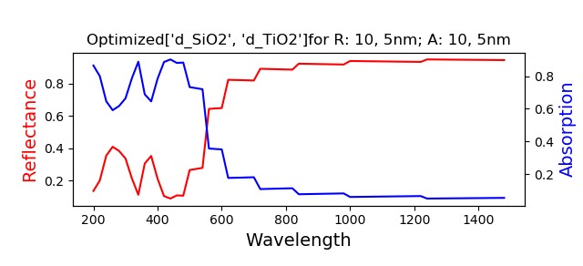
Fig. 4. The simulated reflectance and absorption vs. the wavelength
Due to the multiple variables and the complicated varying ranges, the manually adjusted input ranges for some of them cannot meet the model optimization goal. Therefore, the Genetic Algorithm is used to optimize the variables and achieve an effective multilayer light reflection design. As known that a genetic algorithm is a search heuristic, it reflects the process of natural selection where the fittest individuals are selected for reproduction in order to produce offspring for the next generation. The algorithm includes initial population, fitness function, selection, crossover, and mutation. When Implementing the optimization method, the variable ranges, parameter precision, mutation probability, cross probability, group size, and the number of generations are preset. Especially the population group size and the number of generations are set as 20 and 20 for a demonstration. A complete optimization will be launched in a computational task center. The result of this initial demonstration shows that the reflectance gradually increases along with the generations iterating.
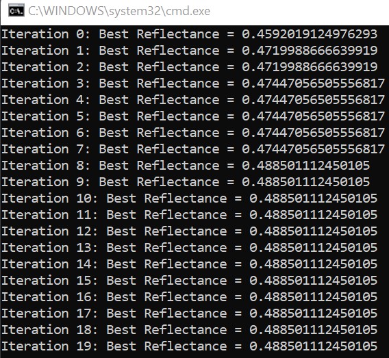
Fig. 5. The simulation result of the genetic algorithm optimization
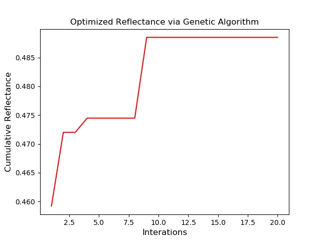
Fig. 6. The iteration plot for the optimized refletance via genetic algorithm
No doubt the reflectance would be pushed close to the optimum value with increasing numbers of population size and iterating generations. This demonstration gives a direction for the multilayer light reflection model optimization, but more needs to be worked out and made to complete the model.
For further modification, the code for this demonstration can be found at: Multilayer-light-reflection-model.
Reference
Keçebaş, Muhammed Ali, and Kürşat Şendur. “Enhancing the spectral reflectance of refractory metals by multilayer optical thin-film coatings.” JOSA B 35, no. 8 (2018): 1845-1853.
Steve Byrnes “Multilayer optical calculation.” arXiv:1603.02720 [physics.comp-ph].
https://www.britannica.com/science/light/Reflection-and-refraction.
Kumar, Manippady Krishna, Sivashankar Krishnamoorthy, Lee Kheng Tan, Sing Yang Chiam, Sudhiranjan Tripathy, and Han Gao. “Field effects in plasmonic photocatalyst by precise SiO2 thickness control using atomic layer deposition.” Acs Catalysis 1, no. 4 (2011): 300-308.
Schürmann, Mark, Stefan Schwinde, P. J. Jobst, O. Stenzel, Steffen Wilbrandt, A. Szeghalmi, A. Bingel, P. Munzert, and N. Kaiser. “High-reflective coatings for ground and space based applications.” In International Conference on Space Optics—ICSO 2014, vol. 10563, pp. 171-179. SPIE, 2017.